Корзина
В вашей корзине больше ничего нет
- Новости
- 0 likes
- 1055 просмотров
- 0 comments
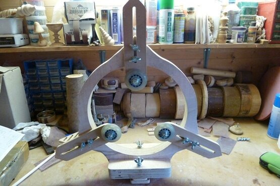
3 wheeled steady for DVR-XP
This is my solution to having a 3 wheeled steady for a DVR-XP lathe for a relatively cheap cost.
I have seen many photos of finished projects, but never a guide on how to make a 3 wheeled steady, so I thought I would create one. This was for my DVR XP Nova lathe so the measurements are tailored towards that, the critical measurement is the distance from the bed to the headstock centre to create the maximum sized steady (of course smaller sizes can be created, but I wanted maximum versatility).
You will need/What I used:
. 400x440 x18mm plywood x2 (main frame)
. 200 x 130 x 18mm plywood x2 (main foot)
. 230x60 x9mm plywood x3 & 230 x 60 x3mm hardboard x3 (arms)
. 130 x 50 x 9mm plywood & 130 x 50 x 3mm hardboard (bed runner)
. 130 x 60 x 9mm plywood & 130 x 60 x 3mm hardboard (foot clamp)
. 2x M8 x 90mmbolts
. 9x M8 x 50mm bolts
. 6x M8 nuts
. 8x M8 winged nuts
. 19x M8 washers
. 8x M8 stringed washers
. 6 x"8 x 22 x 7mm" bearings (can be purchased from a well known online auction site --– ensure the size matches the wheel insert space --– I believe this to be a standard for rollerbade wheels)
. 3 x "62 x 18mm" rollerblade wheels (can be purchased from a well known online auction site --– I went for the smallest diameter wheels I could find to maximise the diameter of item to hold in the furthest range, but to also ensure when the arms wereas far into the centre of the frame it would still hold thin work items before the wheels touched. The bigger the wheel the less range of use you will have).

Step1: Basic Cutting of the Components
Cut out all the components as shown in the diagram below. It is best to use a 9mm router bit to create the groove in the arms. (Option-click or right click to view the diagram full size).

Step2: Glueing the Components
Glue the 2 main frame components together. I used standard PVA for all the glueing.
Glue the plywood and hardboard components of the arms, bed runner and foot clamp together. The reason I chose to laminate the plywood and hardboard together was for extra strength, but to also use the smooth surface of the hardboard on the pieces that connect to the lathe or with the moving washers/bolts.

Step 2
Glue the main foot components together.
Step 3: Further cutting of the Components
Once all theglue on the components has fully dried I further cut out the the details and sanded/smoothed off any rough surfaces. This involved cutting out the inner circle of the main frame and the grooves/slots in the arms. I used a jigsaw for the internal circle in the main frame and a router for the arm slots.
Note you can drill the 9mm holes at any timein this process that is convenient to you. I personally did it once all the conponents were glued, but before I started to connect the individual components together.

Step 4: Creating the Foot
Ensure the main frame slots into the foot cleanly and make minor cutting/sanding adjustments to ensure. The main frame must sit at 90 degrees to the foot and perfectly central (always remember this must align perfectly to the centre of your headstock drive). Glue the foot to the main frame. Once this has dried, glue the bed runner to the foot again ensure this is perfectly central and running 90 degrees to the face of the main frame.

Step 5: Adding the Foot Clamp
If you've not already done so drill the 2 x 9mm holes through the foot, bed runner and foot clamp. From the bottom up insert a 150mm M8 bolt, washer, foot clamp (hardboard surface facing the bed runner/foot), bedrunner/foot, washer, spring washer and finally the wing nut through each hole. slot the steady into the lathe bed and check it runs smoothly, refine the shape of the footclamp if any pinches are felt, like rounding the corners/surfaces.

Step 6: Assembling the Arms
Assembling the arms is best described in 2 parts.
First is connecting the wheels to the arms. assemble the wheel fixture in the following order: 90mm M8 bolt, washer, arm (hardboard surface facing towards the wheel), washer, bearing, wheel, bearing, washer, M8 nut x2. Tighten the first nut so the wheel will turn on the bearings but the assembly does not wiggle. Once the first nut is tight enough, tighten the second nut to it to lock the assembly into place.
Second is attaching the arm to the frame. assemble each arm in the following order (remember it is 2 bolt assemblies per arm): 90mm M8 bolt, washer, arm (hardboard surface facing away from the frame), washer, spring washer and wing nut.

Step 7: Install & Test
Once all the arms are attached to the main frame, the steady rest can be put back onto the lathe for testing. Move the arms towards the piece of work so that the wheels firmly touch the work and tighten the arm wing nuts. Ensure you double check all the nuts are secure before turning the lathe on. Start at a low speed just in case. Once you are happy the steady is performing well (no vibrations due to being off centre or not 90 to lathe bed), then you are ready, with steady and go.

Comments (0)